Технические решения, применяемые в современных турбокомпрессорах

Администратор
Андрей Столяров
Медаль
Сообщений: 252
Санкт-Петербург
144 дня назад
Основные интересные положения статьи Development of VGS Unit (STEP4) for RHV4 Turbocharger//IHI ENGINEERING REVIEW Vol.44 №2, 2011

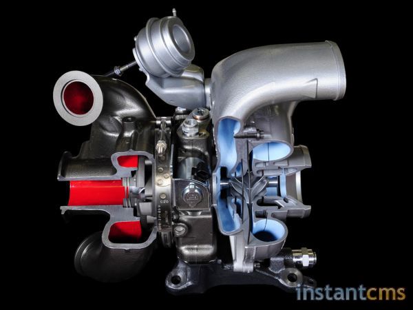
1.Блок РСА механически развязан от корпуса турбины, чтобы на него не передавались деформации.

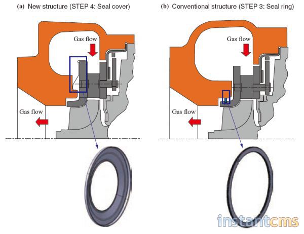
Новое уплотнение блока регулируемого соплового аппарата (РСА) турбины с помощью тонкостенной металлической манжеты, прижимаемой к деталям давлением (слева) вместо традиционного кольцевого уплотнения.
""
Изображение уменьшено. Щелкните, чтобы увидеть оригинал.


2. Применение MIM-технологии (Metal injection molding) для изготовления поводков лопаток РСА. MIM-технология относится к области порошковой металлургии, совмещённой с литьём пластмасс под давлением. Заготовки отливают из расплавленной смеси органического связующего и металлического порошка, после чего выполняется спекание с выжиганием пластмассы. MIM-технологию используют в электромеханических, механических и медицинских устройствах. Наиболее применяемый материал - нержавеющая сталь типа 316.
Специально разработанная технология позволила применить MIM-детали при высоких температурах. Обычно они быстро теряют прочность из-за окисления, но был разработан способ получения деталей с коэффициентом заполнения более 95%, стойких к температуре.

3. Для колец РСА, которые работают в паре с лопатками, применена высококремнистая нержавеющая сталь, снижающая коэффициент трения и опасности заедания при высоких температурах.

4. Выполнена работа по совершенствованию аэродинамических характеристик турбины, лопатки РСА изменены и удалены от окружности диска турбины.
Редактировалось: 1 раз (Последний: 30 апреля 2015 в 14:15)
Администратор
Андрей Столяров
Медаль
Сообщений: 252
Санкт-Петербург
144 дня назад
Статья о турбонаддуве от фирмы MTU(в основном интересна графическим материалом)
Администратор
Андрей Столяров
Медаль
Сообщений: 252
Санкт-Петербург
144 дня назад
Turbocharger

The turbocharger itself is a pretty radical design in its own right. Ford has been trying to achieve more low end torque and top end horsepower for the past 10 years. To achieve that, they initially started with a variable geometry turbocharger on the 6.0-liter Power Stroke. While this gave the turbocharger a much wider operating range, there were still some limits on its performance. With the 6.4-liter Power Stroke, Ford partnered with BorgWarner to design a sequential turbocharger system. This used a variable geometry turbocharger and a fixed geometry turbocharger in series. This system was designed slightly different than a compound system due to the high pressure turbocharger’s variable geometry. The concept was that the high pressure charger would only flow the boost and volume of air that the low pressure turbocharger was pushing but not compress it further. thus no compounding.

Turbo

Turbo_Cutaway

While this sequential system worked well, the cost was high, as the system consisted of two turbochargers. For the 6.7, Garrett, designed a single turbocharger that worked as a sequential turbocharger. The exhaust side of the turbocharger works as any variable geometry turbo. While the exhaust inlets are not side by side, the functionality of the exhaust is the same.

On the compressor side of things, everything is different. The compressor cover is really two compressor covers in one. This is due to the unique design of the compressor wheel or should we say wheels. What Garrett did was to utilize a single turbine shaft to power a single compressor wheel with Siamese profiles.

2011 Ford F-Series Super Duty
With basically having two compressor wheels, they essentially act as a twin turbo system. They will flow twice the mass or volume at the same pressure of a single turbo. When you take into account the reverse flowing heads, and variable geometry turbo, this system is able to provide massive flow at the top end, but also respond extremely well at the lower RPM range.

Intercooler

In trying to obtain the best possible performance, Ford opted to use the first air to water intercooler in the diesel market. An air to water intercooler is much more efficient than a standard air to air.

Traditionally, the boosted air is sent through an air to air intercooler that is in front of the truck. This intercooler has fresh air pass flow between the fins. As the fresh air is moving across the fins, heat is being transferred from the intercooler to the air (which is removing heat from the boosted air). Once the boosted air is cooled, the air is directed into the cylinder heads.

In this new air to water system, boosted air is sent to the air to water intercooler. The intercooler still removes heat from the boosted air, but the heat is transferred to the water that is flowing through the intercooler. The thermal conductivity of water is about 24 times higher than air. So, the water is able to remove much more heat from the air. What this mean is that Ford can reduce the size of the intercooler by almost 75 percent. By reducing the size of the intercooler, there is less parasitic loss throughout the system. This makes the engine much more responsive.

To cool the water, Ford uses another heat exchanger (like a radiator) in front of the radiator. As fresh air passes through the fins, heat is removed from the system.
""
Изображение уменьшено. Щелкните, чтобы увидеть оригинал.
|
Перейти на форум:
Быстрый ответ
Чтобы писать на форуме, зарегистрируйтесь или авторизуйтесь.